3D core
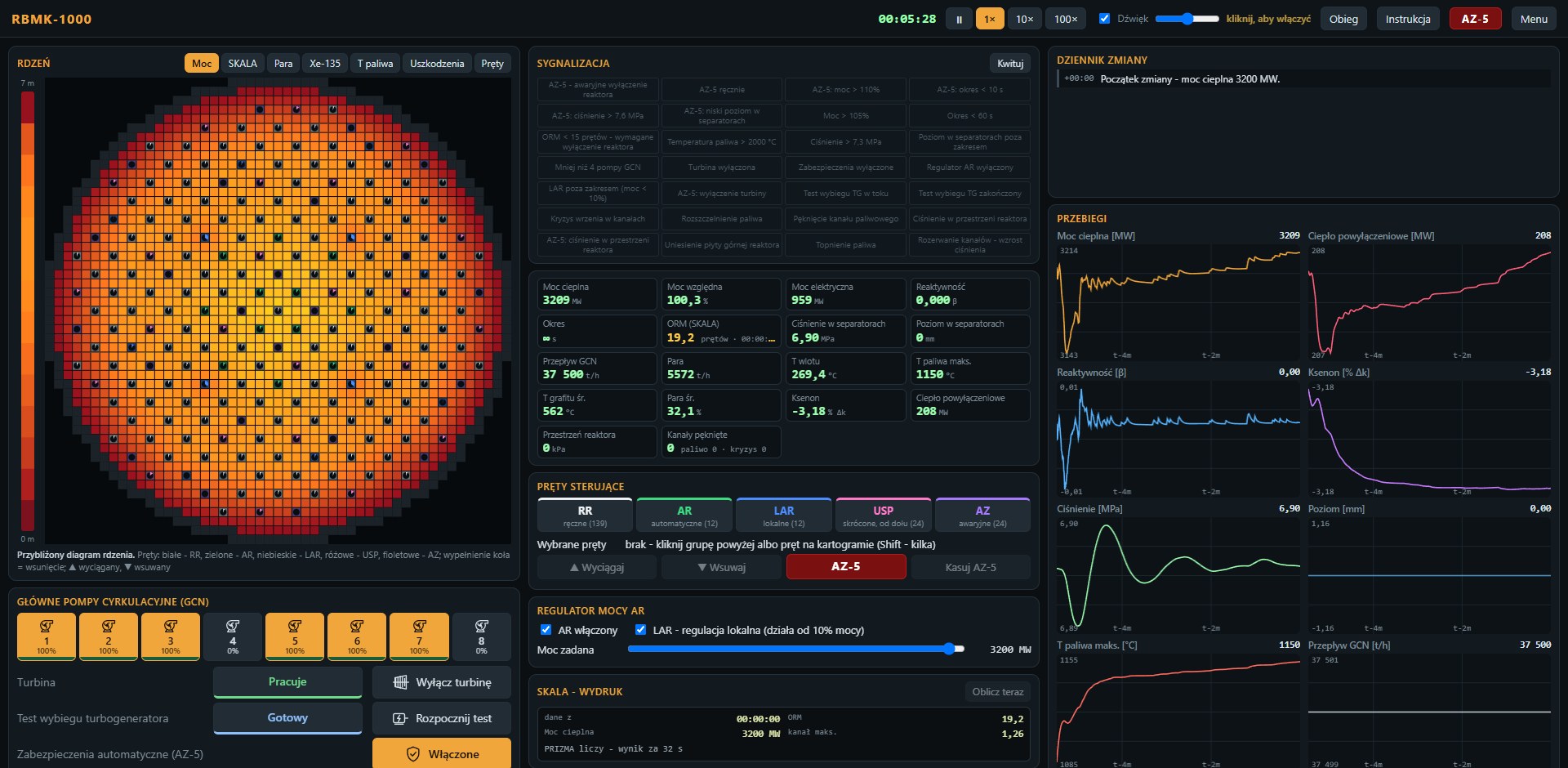
1661 fuel channels and 211 rod channels on a 57 × 57 × 16 grid (25 cm pitch, 50 cm layers). Two-group neutron diffusion - fast and thermal - in about 38 thousand nodes.

 Start simulation
3D neutron diffusion · xenon · void effect · AZ-5
RBMK-1000 simulates a nuclear power unit with a graphite-moderated, water-cooled channel reactor - the same type that operated at Chernobyl. You run the reactor like a control room shift: control rods, power regulator, circulation pumps, turbine, annunciator panel and printouts from the SKALA computer.
It is meant to be fun, but the physics underneath is real: the spatial neutron flux distribution, xenon poisoning, steam in the channels and rods with graphite displacers - the same phenomena that shaped the night of 26 April 1986. Everything runs in your browser, with no account and no installation.
1661 fuel channels and 211 rod channels on a 57 × 57 × 16 grid (25 cm pitch, 50 cm layers). Two-group neutron diffusion - fast and thermal - in about 38 thousand nodes.
Quasi-static model: power amplitude with six delayed neutron groups (β ≈ 0.0046) and the flux shape recomputed on the fly. Reactor period and reactivity in units of β.
Iodine-135 and xenon-135 in every core node. After a power reduction xenon builds up for hours - the iodine pit, local poisoning and power shifts within the core.
Fuel temperature (Doppler effect), graphite (cools for about 75 min) and steam fraction in every channel. Positive void effect - about +5β at full voiding.
RR, AR, LAR, USP and AZ groups with the 1986 design: absorber, water column and a 4.5 m graphite displacer. Full travel in about 18 s - as in reality.
8 main circulation pumps with run-up and coast-down, separators, pressure, feedwater, natural circulation, turbine and the turbogenerator rundown test.
Every 5 minutes the unit computer calculates the power distribution and ORM - the operational reactivity margin - from two full diffusion solutions in a separate thread. You see the state from a moment ago, as the operators did.
Seven fission product groups in every node. After AZ-5 the core keeps heating - about 6-7% of power at first - and the loop has to remove that heat.
Boiling crisis in the channels, fuel failure in a violent power pulse, channel ruptures and steam in the reactor space - with a few ruptured channels the pressure lifts the upper reactor plate.
The unit at its nominal 3200 MW, xenon in equilibrium. A good start to get to know the control room.
The reactor was shut down from full power half an hour ago. Iodine turns into xenon, the graphite cools, steam disappears - try to restart it and see how much reactivity is missing. (In the current model the rod margin is too small to succeed - in reality it was permitted with an ORM of 30 rods.)
The state at about 01:00: after a day of power reduction and a drop to 30 MW the reactor is poisoned with xenon, 46 rods shallowly inserted, the rest withdrawn - as on the map in the INSAG-7 report. ORM below 15 rods (SKALA later computed 6-8). Reconstructed as in the post-accident analyses.
The model is simplified and still being refined. Cross sections and some constants are calibrated to reproduce known values (reactivity coefficients, xenon poisoning, ORM); the literature values are collected in the project documentation.
The positive AZ-5 effect in the 1986 scenario is reproduced: for the first second reactivity hardly changes, then the displacers push water out of the bottom of the core, reactivity exceeds 1β and power rises tens of times in about 4 s - within the range of the three Soviet models in the INSAG-7 report (3.5-80 times). After the power peak come boiling crisis, fuel failure and channel ruptures, and steam from dozens of channels lifts the upper reactor plate - a few seconds after AZ-5, as recorded that night. Numerically it is an approximation: the model gives an ORM of about 19 rods at full power instead of 26-30, and the damage thresholds are simplified. This is an educational simulation, not a safety analysis tool.
Approximate core diagram: the number of fuel channels (1661) and control rods (211) matches an RBMK-1000 unit, but their arrangement on the core map is a regular pattern, not an exact copy of the Chernobyl-4 layout. Reproducing the real layout (from the INSAG-7 report) is planned.
The simulation uses no cookies, no accounts, no ads and no analytics. The simulation runs entirely in your browser - nothing from the simulation is sent to a server. Fonts and images come from the same server as the simulation, with no third-party services.
Browser storage (localStorage and IndexedDB) keeps only settings (language, last scenario, loop window, sound), best task times and saved simulation states. They stay on your device; clear this site's data to remove them.
The server you download the simulation files from may, like any web server, keep standard logs (IP address, time, requested file) for security and diagnostics.
Artwork generated by AI (Malwina graphics assistant, Nano Banana Pro model). Logo lettering: HVD Peace typeface © 2008 Hannes von Döhren (hvdfonts.com). Headings: Oswald (SIL Open Font License).
For comments, ideas or anything else, write to .